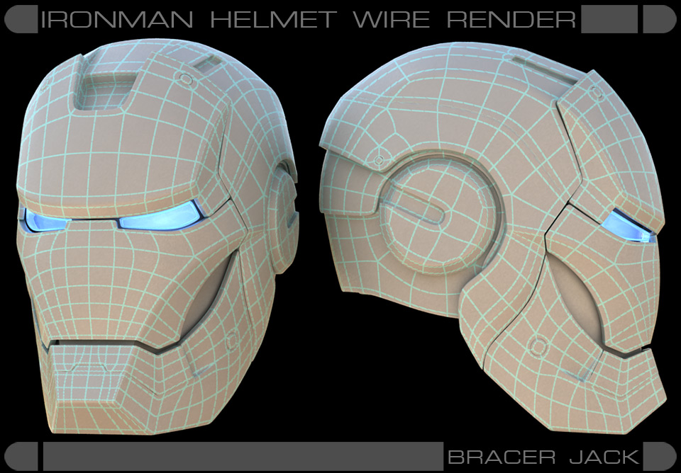
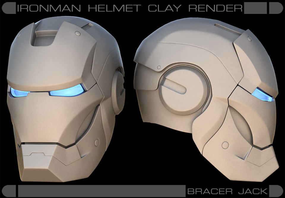
When I first saw Adi Granov’s Ironman Helmet design in the movie, I was overwhelmed by how he had designed something that looked so geometrically simple yet harbored such a high-tech sophisticated look at the same time.
Very naturally, I seek to replicate that design for my own satisfaction.
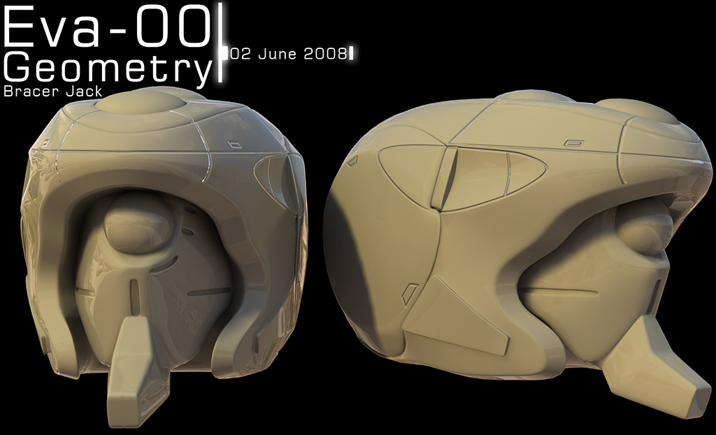
I will also be taking this opportunity to share some of the key points I engage in when modeling hard surfaces, as I have received a number of emails regarding how I model the Evangelion Eva heads which you can see here.
The principle is the same, the key is to “Tighten the Edges” to create that fantastic highlight catching edge fillet effect when the 3D model is subdivided.
In an ideal world, the perfect 3D model is one which edges are all sharp fillets, thereby allowing it to catch perfect highlights everyway it turns.
Please note that this principle should not apply when modeling LARGE scale buildings or anything huge, as the fillet effect would end up giving your large scale buildings that vacuum-formed plastic toy model look.
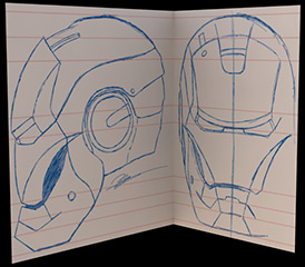
The first thing one must do before modeling begins is to obtain a decent schematic view of whatever they are modeling.
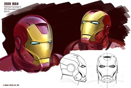
However, if you are as obsessed with the movie version of the helmet design as I am, you would have noticed some small differences.
These differences may not be worth explaining; however, this image is a drawing that originated from the designers themselves.
In my case, I prefer the way the cheek bone “structure” was designed in the final movie version.
I also would like to improve on the design consistency of the back of the helmet and adjust the ratio of the front nasal area curvature, as well as a couple of other details that I personally prefer.
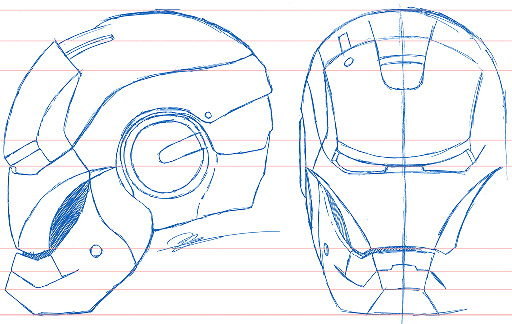
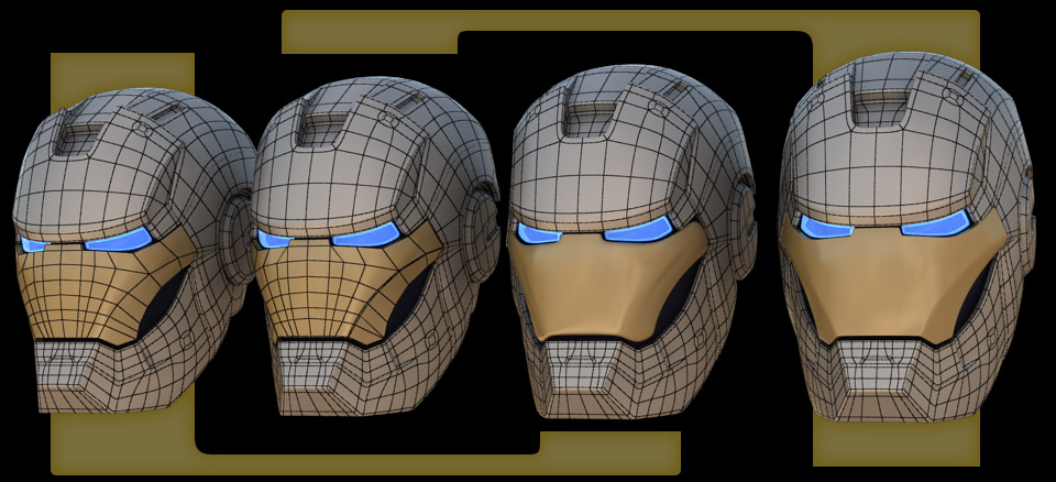
There is a lot of redrawing, refinements and bla bla bla but when all is said and done, these are the final line placements.
Don’t move on until your schematic is dead solid; this is very important for technical modeling.
You can have more leeway for organic modeling when it comes to schematic accuracy.
Bring your schematic into 3D modeling software; I will be using very basic tools, so you can pretty much follow the workflow regardless of which application you choose.
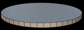
The first thing I did was to create a place holder for the ear “tube”, I did that because it was the only shape I am certain of, it’s just a simple cylinder.
The next thing to tackle is the cheek plate.
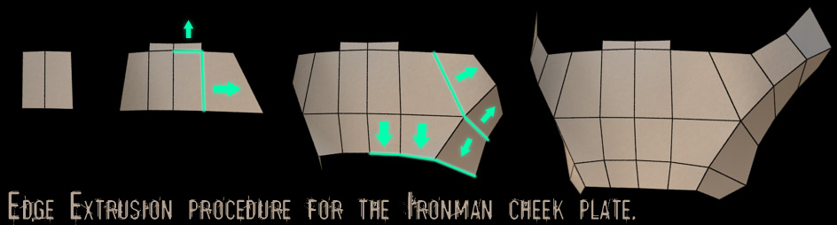
This will be the first and last image to demonstrate what I am basically doing throughout the initial modeling process.
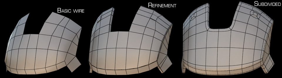
I started out with a simple rectangular plane with symmetry mode on, and I kept on extruding its edges until they are placed at their rightful coordinates repeatedly until the entire structure is complete.
The basic frontal portions of the helmet were completed using the method illustrated in the previous step, along with some simple extrusions.
Nothing complicated; it takes only time.
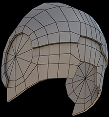
Same goes for the basic back portion of the helmet.
In retrospect, I guess I could have started out with a sphere for the back of the helmet.
But in this case, it began life from a single rectangular plane like the rest of the helmet...Oh my god, the time I must have wasted tweaking vertices to make it look like that when I could have just used a sphere and refined from there instead...
With the basic layout of the helmet complete, it is best to lay out its UVs at this point.
However I will not delve into texture mapping as that is another topic unto itself.
Implement thickness to the back of the helmet along with an extrusion.
The original Ironman Helmet concept was for this to be a two-piece plate, so that one can slide inside another; I am not going to implement this as I do not see how the geometry can actually achieve such a feat.
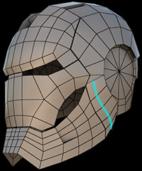
Added one more line to enhance the jaw area.
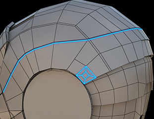
Added one more line alongside the already existing line pattern, implement overall thickness and extrude that thin area in.
Cut a smaller square pattern at the corner using “insert” and then intrude and extrude the smaller polygon to create the bolt.
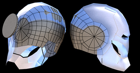
Implement thickness, tighten the edges, and extrude the bolts to completes the forehead of the helmet.
Same goes for the jaw; thickness and edge tightening.
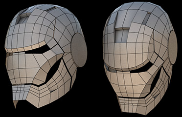
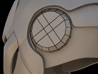
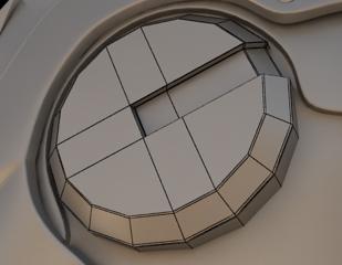
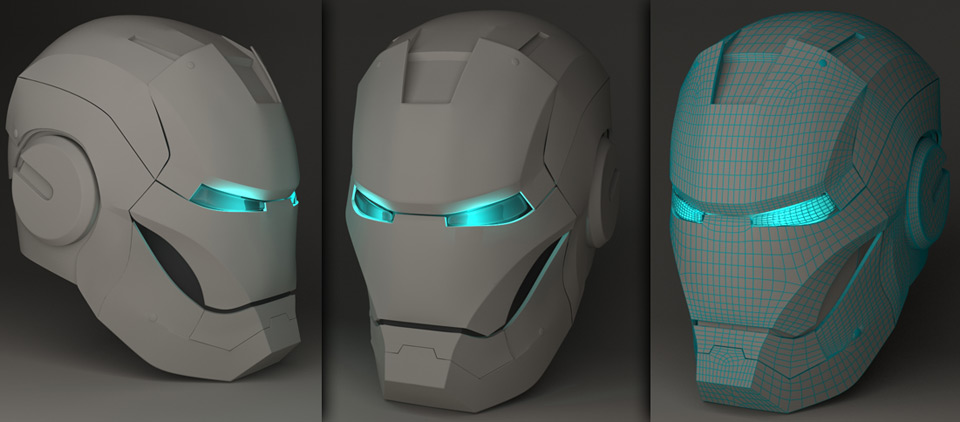
The cheek plate before and after edge tightening in subdivision mode.
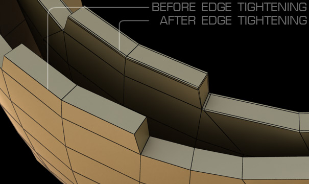
This is what I mean by edge tightening, simply adding one more edge alongside the existing edges.
Most often than not, the subdivision algorithm will not give you what you want.
You may have to adjust the surrounding vertices a little to “appease” the algorithm.
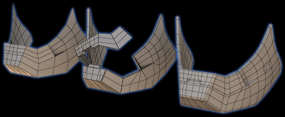
Recreate the ear geometry, start from a 16-section cylinder and chamfer the edges, then merging the points.
Extrude and tighten the edges like so.
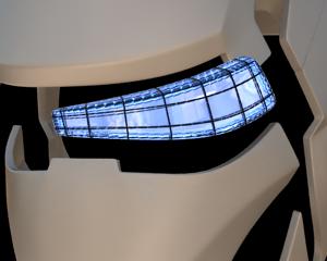
The eye was just a warped box that had its edge tighten for the edge fillet effect.
[To be more exact, it’s a hollow box with thickness so that when I implement the light material, it will diffuse the light correctly like a real physical lens.]
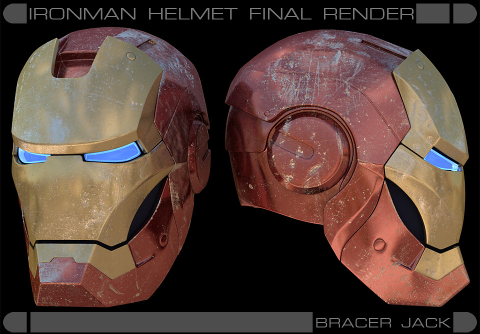
Normally, I like to keep my models perfect and clean. But for the sake of this tutorial, I shall match the dirty, battled look of the helmet as seen in the movie.
It shouldn’t take you long into the tutorial to realize I’ve given an almost “holy grail” status to the Edge Fillet effect.
The fact of the matter is, to me, a 3D model with all its edges and intersections filleted is the pinnacle of 3D modeling perfection.
This myth, however, had long been debunked by my very own observation.
The truth is, by the time you add in all your dirt/rust map to your model, the fillet effect will cease to impress; their sole purpose, catching highlights, isn't really useful for dirt/rust 3D models anyway.
I have come to realize it is an obsession to me that I model like this, it puts a strain on my modeling time and can sometimes make the whole UV mapping process so much more complicated then it needs to be.
I strongly advise that you do NOT behave like me when it comes to implementing Fillet Edges; if it looks right, then it's alright.
Reader’s work:
Every now and then, I receive the works of earnest people who had attempted this tutorial.
This is one of them:
Name: Richard Stothard
From: Kent, England
It was a simple, and easy to follow tutorial with good pictures showing the process, also I had not had much experience with 3Ds Max before attempting this and I managed it fairly easily, which shows how well the tutorial explained and showed the process.
Thank you
Richard :)